Categories
CNC Milling

The Workshop Hurdles…

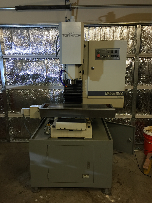
We all love our space to build whatever it is that we are building. The problem is exactly that day when we run out of said space! When I acquired the PCNC1100 in February of 2011, I knew I would be running out of space soon. I was not mistaken; it didn’t take too long…

If memory serves, it was “somewhen” like May of 2012, while I was browsing one of those spam magazines we get on the mail, when I saw a picture that changed my life forever. It was an ad for a Rhino metal building, and apparently for a measly 10K I could have my own gigantor space! YEAH BABY! SIGN ME UP!!!!!!!!!

There was only one dinky little problem… The house we lived in would not allow for such monstrosity. So I chalked it all up to “one of these days”, and moved on with life. And move on with life I did, except my available space did not. Seems to me my error was to come up with the preposterous notion that the way to handle space effectively was to buy larger and larger work benches. I don’t know how I didn’t see how this does the exact opposite, but shame on me for not following like the basic rule of physic we learn in kinder-garden: “matter is that which has mas and OCCUPIES SPACE!!!!!” OK, maybe first grade?

Anyway, I grew the shop up in all possible directions, took over three rooms in the house, completely filled the massive shed, and even then had a problem with space.

Granted that a problem with space seems like a menial problem. But when you are fully packed and have very little space left to put the vise you are using to grab a piece of rod you want to tap, and then realize the only flat space to put the vise is the top of a ladder, when later on you need to move the ladder and that vise lands on your head (because like a total idiot you have already forgotten that you put the blasted vise on top of the ladder), that is when you realize you have run out of space! I don’t know if it was the stars I saw or the pain that ensued, but I must imagine it was at that point in time when I started remembering that metal building ad in the magazine!

NOTE: In the vise’s defense, that blasted chunk of cast iron would not have landed on my head if I had kept my shop tidy. So, a lack of space can also be caused because we are not organized. Or because we have way too much junk and probably it is time to downsize the belongings!

Either way, at some point in time between 2012 and 2015 I decided I have had enough of a cramped space and decided to take action! In fact, I can tell you the exact moment in which I took said action was the XMas Holidays of 2014-2015. For whatever reason I said “SCREW IT! WE ARE MOVING!” And literally, I started packing. Make no mistake about it. When you have been piling $#!+ for so long, packing can take as much as 1.5 years! And that is exactly what it took… We sold the house in September 2016, and to my misery, had to spend almost an entire year stuffed up in a lousy apartment, as finding a suitable home proved nearly impossible.

Parallel to all of this “space lusting” life epoch, Dallas was experiencing its own “life-altering” event. For whatever reason, the entire state of California decided to say “Hey, why don’t we move to Dallas and use our millions of dollars to buy property down there???” Oh, we were in a for a little treat! You see, in California, you need 1 million dollars to buy the most cesspool like dump you can find. Back in 2014, you could buy 2 castles with that amount here in Dallas. Heck, search good and you may get three!

Overnight, a property with space for a workshop went from 300K to 600K and my chances to move into a property with enough space vanished into thin air! I say overnight, but it was actually more like three years. But this is no joke. From 2014 to 2017 I saw house prices running away from my hands at a steadily pace. When I started, 450K was an abomination. At the end, 450K was a frigging BLESSING!

In April of 2017 we finally were able to score and found a home with almost two acres. It was not too far away from technology, it was fairly priced, the school system was quite decent (important for our kids) , and the house looked pretty (my wife’s requirement). Probably, it took a ridiculous amount of time to find a home because I needed to please an entire battalion of people. But that deed is done, so next!

The house came equipped with a three car garage and a putrefying shed. The shed was pack to the brim with all that crap which I don’t need to use a whole lot, and then the three car garage was packed to the brim with the stuff I use more regularly. The media room in the second story was used for computers and the music studio. At the end of the move, I had LESS space than before! You read that right. I had less space! Because as I had specified earlier, on the previous house I only had a two car garage, but the shed was substantially bigger, and the three rooms I had appropriated upstairs, had the equivalent of 1000 SQFT! In other words, before I had almost 1800 SQFT and now I had almost 1200 SQFT. Hence, about 600 SQFT less.

I was already running out of space…

Truly, you have to admit this is a personal problem and the solution is to downsize. Just get rid of all the $#!+ you really do not need. But what $#!+ is that? You know how that works! You never use, you never need it, so as soon as you discard it, WHAMMO! YOU FRIGGING NEED IT!

Ahhh, accumulation! Drug for makers. What a vice! Truly, the only solution was more space.

BUT WAIT! Wasn’t the sole purpose of moving to a 2 acre home to build a frigging workshop? What are you whining about? THIS IS IT! Build the blasted thing and be done with the so called lack of space! Right?

Well, not so fast… Turns out the city where I reside would not let me build a metal building. WHAT! How did you fall for that one? What a tool! Yeah, in here, my dream of erecting that awesome metal building I had come upon back in May of 2012, was not a possibility. But I knew that, and I was so desperate for more space, I had convinced myself a wooden and brick structure was the right way to go! Except if you recall, when I saw that magazine ad, the metal building was 10K!

Now, let’s be honest. There is really not much of a way to get a decent metal building for a paltry 10K. They get you to salivate and dream with that number but in all reality, at the end of the day it is going to be way much more than 10K! Specially, when you start increasing the footprint and eventually lead yourself to something like… I don’t know… 2400 SQFT??? Yeah, no frigging way you are getting that puppy for 10K!

So I had decided I wanted a 2400 SQFT workshop because the goal here is to approach death without having to say “DAMN IT! I RAN OUT OF SPACE AGAIN!” And I understand there is a notion that there is just no frigging way you can ever build a workshop with enough space, as sometime in the future you will fill it up anyway. However, I have to say 2400 SQFT should be frigging enough for a very long time! So that was the dream!

Imagine my jaw crushing as it felt into the ground when I talk to contractors to build a 2400 SQFT wooden structure. HAH! 10K dream was shattered when I realized there was no such thing as a 10K building, but what I didn’t realize was that a 2400 SQFT wooden structure was an impossibility! In essence, and because of the stupid brick requirement, a wooden / brick structure is 4 times more expensive than a metal building.

In other words, a 2400 SQFT metal building would set me behind about 60K-80K (depending on how much junk I add to the equation) and for that amount, I might be able to build a 600 SQFT wooden structure. WHAT THE HECK!!!!????

These were depressing years. My dream to build a workshop was shattering like a wine glass clashing against Jupiter’s atmosphere. I was dead inside. All this work, for years and years, to build a blasted workshop and turns out, it was not possible??? PHOOOOOOOOOOCK!!!! (if you are wondering, that reads like the word that starts with F, followed by an U and ending in CK – I am trying to keep this web page PG-13, people!)

And then one day my wife comes home with “I have good news for you!” I don’t know why, but I had a tingling sensation this had to do with the workshop. I had already forgotten about my dreams by June 2019. Two years of looking for loop holes to erect a metal building had proven futile. But an angel came out of the wood works, and that angel was no other than Texas Governor who basically said “SCREW YOU CITIES! From now on, you can’t demand any construction material! If it is up to code, anybody can build whatever comes out of their heinies!!!!” OK, maybe that wasn’t too PG-13… And those were not his exact words either…

WHOA, was there celebration that day! Immediately started contacting contractors and getting my quotes. There was one wimpy little catch! I needed to wait until September 1, 2019 for the new law to come into place. That gave us some time to gather all of our thoughts. By September 1, 2019 I had the contractor selected and the paperwork commenced. It took a while to get all the documents in place, but by December 2019 we had a permit and we set to start as soon as possible in 2020. The guy had some projects in the works, but in February 2020 we broke ground.

And the rest is history! At the time of this writing, all I am lacking is electricity. However, I have been moving a good bunch of my belongings as I do not need electron flow to perform that task. A couple lights would come in handy, though…

Anyway, these youtube videos portray the steps required to get this lovely monstrosity put up!

Categories
CNC Milling

Some Projects To Work On

Not certain when I will be able to work on any of these, but these machines seem like a tremendous addition to any workshop. And they are all quite easy to make!

Yes, I know these folks need to eat and feed their families, but since I am just a hobbyist, it makes little sense for me to spend thousands of dollars on something I can easily make for much less. If I had a factory, however, I wouldn’t waste my time manufacturing them. I would just buy them up!

Tapping Machine

I could do tapping on the Tormach, but what a frigging pain! I often end up doing them by hand. Again, WHAT A FRIGGING PAIN!!!! So which one is less painful? Obviously tapping by hand has been winning, but this little machine I just saw is by far THE WINNER!!!

Magnetic Box and Pan Brake Sheet Metal Machine

This one I saw a while ago. What a tremendous idea! I mean, it is basically a simple electromagnet and then a pan brake. How hard could it be to make one of these? I work with electromagnets every day so to me this is peace of cake. The brake is something which will not necessarily come as easy, but come on… It’s a frigging hinge! How hard could it be?

Precious Plastic Recycling Machines

This is more than just a machine. Is a set of machines concocted to aid in the goal to recycle plastics the “easy” way. The premise is that if everybody had one of these machines, you could shred and extrude your own plastic. Sounds reasonable but it really doesn’t. I completely doubt the entire human race will go through hoops to have a bunch of machines in their homes to shred plastic, inject plastic into molds or do your own filament extrusion.

For makers, however, these machines could become quite the good tool to have! I think the major hurdle in these machines is the requirement of a large and bulky motor to move at very slow speeds with decent torque to push the plastic in whatever state it is in. I will have to think about how to do this one which smaller motors, because I don’t have a big large pile of industrial motors lying around…


Categories
CNC Milling

Darth Maul Master Replicas Dual Lightsaber Coupler

One of my CNC Dude YouTube viewers was having some kind of a duel with a Jedi and broke his Master Replicas Darth Maul Dual Lightsaber coupler. He asked if I could be commissioned to build this part and although many people have asked whether I am willing to build parts for a price, the unfortunate truth is that I lack the time to undertake pretty much any project I can dream on. What I thought I could do, however (and since I happen to be the proud owner of one of these replicas), was draw the coupler in my CAD tool and provide him with a drawing he could then use to commission some machine shop time (maybe a local Maker Space???).

I am going to say the drawing came up almost perfect, except for the thread which is a little bit past my level of expertise. Had I been a mechanical engineer, this would have been an embarrassing fact to admit to, but as an electric engineer I have to say I am blown away by the fact that I actually draw the darned thing! I imagine any knowledgeable machine shop guru should be able to do the thread correctly. So be aware if you download the files for this project, that I am not certifying the thread to be correct. If I happen to know how to fix it, I will most likely update this posting and advise accordingly.

Now, here are a few points which I want to add to this report. As I searched on the web (mostly forums), it became apparent that this part brakes a lot. As I was analyzing the part in my hands, I came to the conclusion the cylinder in question is the product of a casting procedure.  I am not certain of the material (aluminum, zinc?), although I think it is aluminum. What I can tell you with 99% certainty is that it wasn’t machined. For example, the coupler I was taking measurements from is not perfectly round (you can only notice this by measuring with a caliper, not by touching it). Whereas flaws of this nature make perfect sense as them being artifacts from the cooling process, there is no way I can envision them as being the product of a turning operation. But to be honest, it is pretty obvious it is a casting by just looking at it.

Will an actually machined part come out to be stronger? That is a question for which I would love to have a good answer…

On my search, I also saw that at some point in time you could have bought this part for $20. I am going to tell you something! If you can find this part either on eBay or one of those lightsaber depots for $20, feel free to rip it without even thinking twice about it as I can assure you there is no way you will be able to get this part manufactured in the once or twice quantities for $20. Maybe $50-$100 if you are lucky? So my advice is to find a machinist friend and let them make the part just for the fun of it. Heck! That is what a hobby is all about!

One last important detail. The model I am about to show (and the one for which I am providing drawings) is for a solid as opposed to the real thing which is made of two parts bolted together with an 8×1.25 mm socket screw. If you were to machine this, I don’t see why you would want to make it in two parts (unless of course you want to recreate the scene where Obi Wan chops off the unit with a single blow…) Feel free to get creative and decide how you want to make this into two parts, but if you have these lightsabers then you already know.

And without further ado, this is what the model looks like:

DarthMaul_LS_Coupler

DarthMaul_LS_Coupler_angle DarthMaul_LS_Coupler_side

You can download a drawing with the measurements and some notes here: (WARNING!!!! THE THREAD IS NOT ACCURATE!!!) Darth Maul Coupler Drawing PDF

Categories
CNC Milling

CNC TOO Clean And Ready To Go!

IMG_0529 IMG_0530 IMG_0531 IMG_0532 IMG_0533 IMG_0534 IMG_0535 IMG_0536 IMG_0537 IMG_0538 IMG_0539 IMG_0540 IMG_0541 IMG_0542 IMG_0543 IMG_0544 IMG_0545 IMG_0546 IMG_0547 IMG_0548 IMG_0549 IMG_0550 IMG_0551 IMG_0552 IMG_0553 IMG_0554 IMG_0555 IMG_0556 IMG_0557 IMG_0558 IMG_0559 IMG_0560 IMG_0561 IMG_0562 IMG_0563 IMG_0564 IMG_0565 IMG_0566 IMG_0567

Categories
CNC Milling

ROTJ Lightsaber Project Files

One of my viewers has asked where can he download Luks’s ROTJ Lightsaber Replica files? Well, how about here:

Luke_ROTJ_Lightsaber_Assy_Parts – If you have inventor, you can take a look at the assembly and part models in IPT format

Luke_ROTJ_Lightsaber_Drawings_1-7-2016 – These are DWG and IDW files with the drawings. You should be able to get a free viewer and check the measurements that I used.

Do note I have no idea what the real measurements are. It is most likely none of these measurements are actually the ones from the real thing. In fact, considering the prop was developed in England (or so I think), chances are the original replica was built using metric measurements, whereas my replica is in inches. This is kind of fascination (although I think the right word would be idiotic) considering inches are an unit within the English or Imperial system. But I am most positive this religious discussion is close to half a century old, so will not continue fueling it here…

Anyway, in order to get the actual measurements I would have needed to buy a prop. If I had a couple million dollars lying around I could have easily purchased the actual original replica. Last time I checked, my bank account wasn’t enjoying from such a deep level in the fund arena. I could have perhaps purchased one of those Master Replicas, but I am not certain how accurate those are anyway. Just because they are licensed doesn’t mean Mark Hamill is going to grab one of them and say “Holy Cappuccinos Batman, is this the one I used on that set 30 years ago or what?”

At the end, I don’t really care about being super exact with my measurements for a few reasons:

1. 99.99% of the people who will ever hold my replica on their hands are not millionaires either. As a result, chances are they do not own one of the Elstree props in which case it is virtually impossible they will ever be able to compare both of them and say something “Hey wait a minute… Who are you trying to fool here?”

2. The great majority of people who have actually held my replica have needed to change their diapers shortly after. This right there tells me they have no idea this thing is not following “The Quintessential Prop And Replica Guideline Handbook Of Ultimate Ruling And Armageddon” available at your local Barnes and Noble.

3. I am already married and have a kid, so Darwinian Survival is now based in my ability to maintain my offspring alive until he can reproduce, not how accurate this replica is and how many ladies out there go through wetting sensations as they check my piece. I mean, my prop… I mean, the replica… Ah, screw it! You know what I mean!


Categories
CNC Milling

The VFD Conundrum

After bringing my second PCNC1100 almost back to full fledged life, there is still one item puzzling me! The spindle on this machine moved at 2X the command speed. I know the belt is where it is supposed to be, the pulley has been assembled correctly and MACH3 has been configured properly (there really isn’t much you can play within MACH3.)

Having two machines, you would imagine it would be piece of cake to compare both VFD units and VOILA! find the difference, right? ERRRR!!! WRONG-O!

As it turns out, comparing both VFDs does show one difference except that it doesn’t make any sense.

Before I go on, allow me to post the Emerson Industrial Automation Commander SK’s manual in case you want to drill your head with the preposterous 200 page long manual in PDF format: COMMANDER SK MANUAL.

Here is where this is squashing my brain:

1. A quick look at the manual shows there is one parameter (#24) which deals with customer scaling factor. You would imagine that the machine running at 2X would have a 2.0 in this position and the other machine a 1.0. Except they both have a 1.0 at this position. OK…

2. As I keep comparing parameters one by one, the only where I see a meaningful difference is address 65 which according to the manual is an User Configurable Parameter. Clearly Tormach must have done their own programming and used this parameter because the default is supposed to be 0. On one machine I see 8.5 and the other 14.3. Not twice, which is what puzzles me.

You would imagine the solution is to change address 65 so they match, but not so fast! What if this parameter is meant to be different from machine to machine? Had they been 2X the size that would hint to this being the place to change, but they are not 2X apart!

Or maybe there is something else I am overlooking? Everything is possible!

UPDATE 2/5/2014

Yes, EVERYTHING IS POSSIBLE! And in this case what was possible (not that I thought it was impossible) was my own moronicity.

This is one of the simplest solutions I have encountered in my whole life. The problem occurred because I thought I was following the spindle speed configuration instructions, except that I wasn’t. To make the story short, when you run PCNC COnfig to type in that number the VFD reads while running at 500 RPM, you have to be running in low gear. If you happen to have the machine in high gear, you will go at twice the speed. ERRRRR!!!!

Notice you need to configure the low gear both physically as well as in MACH3. Then run the spindle at 500 RPM and whatever you read on the VFD display, you enter within PCNCCONFIG.

This dinky little detail was present on both the PCNC 1100 manual as well as the Windows Application and somehow I still didn’t see it. Oh well problem solved and many more to come!


Categories
CNC Milling

Further Tapping Nightmares Resolved

Sometimes I pose the following question: “Why couldn’t things be simpler?”

And here is the answer: Because if they were, what would there be to fill our life with grief, ragged tympanums, sandy throats and broken walls?

After gathering all of my data on how to tap, I decided to go into Sprutcam and enter the threading operation only to find out it was compiling without doing anything at all. That is, the process was being generated with an empty set of steps. Needless to say, this wasn’t going to work very well…

I do have to admit that the ability to see a simulation is crucial! To have had to go through this nightmare without actually seeing what the program was attempting to do would have taken way much more than the close to two hour that it shaved from my life.

But anyway, here is what happened:

After selecting my centers as you normally do (Double click on one of the half surfaces of the holes you want to apply the Hole Machining operation and press Center under the Job Assignment tab) I chose the tool as my #8-32 Tap. It looks something like this:

ToolSelection


If you are a CAMing expert, you will be able to spot what the problem is by just looking at this page. If so, you will be able to correct the issue in seconds. Perhaps this is why it took me anywhere in between 3600 to 7200 seconds (across two days of pulling my hair) to finally figure this out. I will get back to this…

Next step is to select the Feeds and Speeds. This is where most of the documentation on the web is available and it is also one of the topics from my previous post. Pretty much everything out there will tell you to use 300 RPM, but after reading on some forums, this appears to be too slow a speed rate. Anyway, there are tables and there are pieces of software which will tell you what RPM to choose. Then you divide this number of RPM by the thread pitch, and that is your feed. In my case I chose 800 RPM, and since this is an 8-32 screw, 800RPM/32TPI = 25 IPM.

FeedsAndSpeeds2

Finally, we need to select the actual strategy which is the tab where we specify the “tapping” operation. There really is not that much to it. By following Tormach’s recommendation, all we need to do is make every value equal to zero, except the dwell time which should be 0.3 seconds. Everything else (not shown on the picture for some weird capturing reason) is as default.

Strategy

If everything is right, you should just be able to press the “RUN” button and get it over with, right? Err, wrong! Because as it turns out, everything is NOT right. As I detailed earlier, there is a bug in one of the previous screens. Were you able to spot it? Let me show you the result, which is so frustrating here is where the wall banging session begins…

SprutcamFailedOutput

Notice there is nothing below the Threading operation. You may be wondering what do I mean by nothing when clearly there is something there. Well, not really. The stuff you see here is basically a preamble. In this case, a preamble to NOTHING! What you want to see is this:

SprutcamCorrectOutput

As you can see, Sprutcam has now applied the Threading operation to my 4 holes, whereas on the previous instances there were no holes to be found. What an A HOLE!!! But as it turns out, it was me the A Hole, or in this case the idiot not realizing there was a bug in my programming.

Let me give you a list of what it isn’t so you don’t waste your time trying all of these alternatives on your next tapping endeavor:

1. It is not a bug with Sprutcam.

2. It is not a matter on how you select the hole centers. You still do it like you have been doing it before and you do not need to select both half surfaces of the screw. One is all you need!

3. You do not need to modify the hole properties on the Hole Editing window.

4. You do not need to…

You know what? I bet what you want to know is what is the frigging bug and what are all of the things that I tried to no avail.

The bug is actually quite simple! If you go back to the tool selection picture, you will notice my tap has a diameter of 0.099″. This is a copy+paste error from when I copied the #6-32 tap into the new #8-32 tap. The problem is that to make an #8-32 threaded hole, you need a 0.140″ drill. If you tell Sprutcam to use a tap that is way smaller than this already existing hole (e.g. 0.099″), then Sprutcam is going to say:

“Well, I would run this operation but there is no material to be removed, so I am just going to skip it.”

WHAMMO!!!!!! I would be pissed at Sprutcam, but as it turns out this is the right answer. Why would you work arduously in doing something which is already done? The solution then is to specify the tab to have a diameter larger than the existing hole so that Sprutcam can be happy and feel like it is removing some material with the tap. Hey! SW suites also want to be happy!

What eventually solved the problem for me was to use a tap diameter of 0.14″. And with that I can now finally go to the machine and get the darned part manufactured. I was supposed to finish all of this on Friday, but Sunday will have to do. Long day ahead, so let me get busy!


Categories
CAMing

Tapping The Heck Out Of The Heck!

AHhh, Tapping! That activity invented by the human race which is destined to provide countless hours of hair pulling, carpal tunnel, broken taps and all sorts of vocal maladies launched into mid air while fueled by disproportionate demons.

Unless you do it right…

Except it is not that easy to make it right!

One of the beauties about using CNC machines is that it removes the burden of tapping from your shoulders. Is the tap at 90 degrees with respect to every possible axis on all parallel universes? CHECK! Is the right force being applied? CHECK! Will I break a tap? Well, it won’t be you, but the machine. CHECK!

The only problem with using a CNC machine to do your taps is if you, like me, do tapping every three months. Although most of the time I do it I get it right, the truth is next time I need to do it I have COMPLETELY forgotten how on Earth I did it. When that happens, I find myself looking through all of my reference material and wasting about two hours of time before I can let Sprutcam compile the G Code.

And that is where I am today as I write this post. I have completely forgotten how to do this, so I have decided it won’t happen again. Next time I have forgotten (which will be in a couple of days…) I will simply tune to this blog and WHAMMO! Problem solved!

First place I go to check how to tap the crap out of my material is Tormach’s Blog. Although this posting is practically ancient (more than 4 years old), it has some of the nuggets which get my memory cells jump started:

http://www.tormach.com/blog/tensioncompression-tapping-and-sprutcam/

Unfortunately, there are still a few questions I can’t answer by looking at the 4 pictures they have provided. For example:

1. How do I choose the RPM?

2. Are Aliens visiting us?

And so I then tune to John’s (from NYCCNC) Youtube channel and watch the next video where I still don’t get much of an answer on how to select the 300 RPM but I kind of answer question #2. Just kidding man! This video has a bunch of very useful information!

NOTE: I didn’t ask John for his permission to link to this video, so I truly hope he doesn’t send a horde of lawyers to pursue my sorry butt. John, if you want the link removed feel free to let me know!

I did a quick search and found this table which gives a bunch of RPM rates for different materials and depending on the screw. It gives us the same equation we have seen over and over (Feed = RPM / Thread Pitch). The RPM values, however, is what blew me away! If I have been using 300 RPM for aluminum, I have been doing this wrong!

http://balax.com/sites/default/files/Suggested-Tapping%20Speeds.pdf

Another option is to use GWizard. I thought of giving this a try and found that 300 RPM is also a big mistake! Intriguingly, the GWizard output is not identical to the table I linked above. Then again, this table may be meant only for those taps. Right? How would I know? What I found interesting is that according to GWizard, the same RPM applies for both aluminum and plastic. At first I thought the program was not updating the selection, but choosing Stainless steel quickly modified the values to smaller numbers, which makes sense. Why is GWizard different to the table?

And why on Earth is everybody assuming 300-500 RPM for aluminum!!!!

Well, no fret. It is time for me to give this a try and hopefully I don’t send my scarce number of taps into hades. At least now I know that a few weeks from now, when I need to tap again, a guide on how not to soil my underwear will be available!

Categories
CNC Milling

Learning a BIG Lesson!

For three years I have been using my PCNC1100 in the low speed range. I was under the impression that cutting aluminum at 1800 RPM was more than enough. And for some passes, it was. However, when doing pockets and 2D contours I was getting a ridiculous amount of chatter which results in the most horrendous finish.

I kind of solved the problem by taking lighter cuts and repeating this a gazillion times.

At the same time, I have been seeing multiple CNC users employing a tool better known as GWizard. It became apparent that perhaps I wasn’t utilizing the right parameters when cutting my materials. Perhaps I too should be using this software offering…

Unfortunately, what ticked me about GWizard was the fact that this was a subscription tool. To me a subscription is paying a yearly fee to get a magazine in my mail box (at a cheaper price and before it hits the book stores) and at the end, if I want to continue receiving the magazine I pay again. The difference between a magazine subscription and a GWizard subscription is that at the end of the year I still have my magazines but I have no GWizard.

And so I decided to never employ this intriguing tool. I decided I was going to “wing it” on my feeds and speeds! What could go wrong, right?

SHAME ON ME!

Luckily, for my cheap ass, the GWizard folks decided to team up with Tormach and offer a version better known as GWizard Lite with a Horse Power limitation, but life support. To me this was the opportunity to enjoy from this knowledge base, so during one of the specials I took the plunge and got GWizared.

Let me tell you something. This tool is not a tool. It is a window into a parallel Universe! In the Universe where you do not have the tool, you will be breaking bits, getting lousy results and wondering why the tell nothing works as it should. In the other parallel Universe, the one where you decided to humble up and let the experts tell you what you are supposed to be doing and how, you will start to get the results you have been wanting, at a considerably faster pace.

I am still not a GWizard expert, but by just using the tool a few times, I have been able to correct so many misconceptions, the software is in essence paid for. Had I gotten it months or years ago, I would have saved on countless mills and drills I have viciously sent into HSS Hades.

And so I have changed my mill from low speed range to high speed range. A quick set of very short experiments have showed me that in fact GWizard’s suggestion is about one trillion times better than my “wing it” approach.

My apologies to Bob Warfield and the GWizard team for not seeing the light any sooner!


Categories
CAMing

Sprutcam Licensing Trick

I do not recall how much I paid for my Sprutcam license, although I imagine it must have been somewhere in the vicinity of $1500.00. There are many CAM software suites out there, and although Sprutcam has managed to piss me off countless times, I am still confident it is one of the best deals out there.

What truly pisses me about Sprutcam, as well as any other software based on the ultimate form of mistrust, is the darned dongle crap. It truly bugs me for two reasons:

1. Dongles imply that you can only use the SW on one computer (which is of course the main reason why there is a dongle in the first place) and

2. I still wake up at 3:00 AM in the morning fearing my dongle has been lost in which case I have miserably wasted whatever amount of money I paid for in the first place.

Item #2 will plague me forever as there is no legal way of copying this dongle in case something heinous happens. Item #1, however, I set myself to solve.

But why?

Well, as it turns out, Murphy’s law makes it imminent that the most that you need a software to run in only one computer, the more that you will need to use it in two.

My main computer is inside the house, on the second floor, might I add. This is where I work my designs and do the CAMing. As I specified, it is in the second floor which brings us to the Murphy’s law stating it is 100% certain the better you have done a CAM in the second floor of your house, the more probable it becomes you will find bugs while you are in the first floor.

Of course I can’t have my PCNC1100 milling machine in my second floor, but I can’t have the main computer on the first floor either, so what to do?

Well, I decided to install a second computer to do quick fixes whenever I am running a job in the garage, where the CNC machine is located. Unfortunately, for this to work, I would need to be moving the dongle up and down on a continuous basis. This is a clear violation to the Murphy’s law which states that as soon as you start moving up and down that ridiculously expensive item you dread to lose, you will either loose it or misplace it whenever you need it the most!

Once again, what to do?

I thought of installing an USB switch so that I could remotely specify which computer is entitled to use the USB dongle. It doesn’t work 100% perfect because every now and then the USB switch develops a temper, but for the most part it has become the solution.

This is the USB Switch I am using, and you can find it here: http://www.amazon.com/Cables-Unlimted-USB-Automatic-Switchbox/dp/B0006N213K/ref=sr_1_10?ie=UTF8&qid=1393466095&sr=8-10&keywords=cables+unlimited+usb+switch

This solution still poses a problem. Sure, you can now have two computers to claim the dongle, but how on Earth are you going to hook two computers into this thing when one of them is on the second floor and the second one is on the garage? USB standards forbids such a long cable!

No worries! The solution comes in the form of an USB cord expander which utilizes a CAT5 cable connection, or this: http://www.amazon.com/SANOXY%C2%AE-over-Extension-Cable-Adapter/dp/B003BDMK3S/ref=sr_1_1?ie=UTF8&qid=1393466340&sr=8-1&keywords=USb+RJ45

I have been using this solution for three years. In that time, one of the USB extenders died so I had to replace it. But man, at less than $10, who is counting?

So here you go! An entire solution for less than $30 which beats buying two licenses of Sprutcam. Now, if I were a Rockefellarian, then I could buy 2 licenses. Although the truth is if I was a Rockefellarian, I would have a shop so awesomely big, my main computer would be besides the milling machine.